LittlePrinter: Unterschied zwischen den Versionen
HKay (Diskussion | Beiträge) add pictures and chip names |
HKay (Diskussion | Beiträge) add some info about the interior of the printer itself |
||
| (5 dazwischenliegende Versionen desselben Benutzers werden nicht angezeigt) | |||
| Zeile 1: | Zeile 1: | ||
= BERG = |
|||
| ⚫ | |||
{| align="center" border="0" |
|||
| |
|||
[[Datei:Little_printer.jpeg|200px|thumb|right|The Little Printer by BERG]] |
|||
A few years ago a design company from London called "berg" introduced the Little Printer. The device basically is a small printer that prints various feeds provided by berg on a daily basis. Feeds like twitter, newspaper articles, trivia and sudoku. For that it uses regular receipt paper. ([https://www.youtube.com/watch?v=B_bytm9_P4w promo video]) |
A few years ago a design company from London called "berg" introduced the Little Printer. The device basically is a small printer that prints various feeds provided by berg on a daily basis. Feeds like twitter, newspaper articles, trivia and sudoku. For that it uses regular receipt paper. ([https://www.youtube.com/watch?v=B_bytm9_P4w promo video]) |
||
The pricetag was 250 Euros. |
The pricetag was 250 Euros. |
||
In 2015 the company went into hibernation but kept the servers running for the rest of the year. Now, in January 2016 the devices are practically useless without the backend servers. I got mine dirt cheap on ebay. [[Benutzer:HKay|HKay]] |
In 2015 the company went into hibernation but kept the servers running for the rest of the year. Now, in January 2016 the devices are practically useless without the backend servers. I got mine dirt cheap on ebay. [[Benutzer:HKay|HKay]] |
||
|- |
|||
| |
|||
= The Bridge = |
|||
[[Datei:Little_printer_bridge.jpeg|200px|thumb|right|The Little Printer bridge by BERG]] |
|||
The printer does not talk to the internet directly. That's what the extra box called "bridge" is for. It has a RJ45 connector for Ethernet and a ZigBee module. |
The printer does not talk to the internet directly. That's what the extra box called "bridge" is for. It has a RJ45 connector for Ethernet and a ZigBee module. |
||
|- |
|||
| ⚫ | |||
| |
|||
| ⚫ | |||
[[Datei:Little_printer_bridge_v1.4_top.jpeg|200px|thumb|right|top of bridge v1.4 PCB]] |
[[Datei:Little_printer_bridge_v1.4_top.jpeg|200px|thumb|right|top of bridge v1.4 PCB]] |
||
[[Datei:Little_printer_bridge_v1.4_bot.jpeg|200px|thumb|left|top of bridge v1.4 PCB]] |
[[Datei:Little_printer_bridge_v1.4_bot.jpeg|200px|thumb|left|top of bridge v1.4 PCB]] |
||
| Zeile 30: | Zeile 40: | ||
The rest is voltage regulation and logic |
The rest is voltage regulation and logic |
||
To connect to the board via a serial link I used the "SparkFun FTDI Basic Breakout". The RX,TX and ground pins are indicated in the picture above. Connect "RX"(receive pin) to the "TX"(transmit) pin on the FTDI board and the other way around. Also connect GND to GND. Make sure you have the 3.3V version as the 5V version would likely fry the board. |
|||
|} |
|||
| ⚫ | |||
| ⚫ | |||
Here is the boot chatter of the bridge. |
Here is the boot chatter of the bridge. |
||
The system is a AT91SAM9G20 at a clockspeed of 396 MHz running Linux with a kernel version of 2.6.36.4 in April of 2013 |
The system is a AT91SAM9G20 at a clockspeed of 396 MHz running Linux with a kernel version of 2.6.36.4 in April of 2013 |
||
| Zeile 52: | Zeile 63: | ||
Now we just append init=/bin/sh to the end of the boot arguments. And continue booting. |
Now we just append init=/bin/sh to the end of the boot arguments. And continue booting. |
||
<pre> |
<pre> |
||
setenv bootargs console=ttyS0,115200 root=/dev/mtdblock6 mtdparts=atmel_nand:128k(bootstrap)ro,256k(uboot)ro,128k(env1),128k(env2),2M(linux),16M(config),-(root) rw rootfstype=jffs2 init=/bin/sh |
U-Boot> setenv bootargs console=ttyS0,115200 root=/dev/mtdblock6 mtdparts=atmel_nand:128k(bootstrap)ro,256k(uboot)ro,128k(env1),128k(env2),2M(linux),16M(config),-(root) rw rootfstype=jffs2 init=/bin/sh |
||
| ⚫ | |||
| ⚫ | |||
</pre> |
</pre> |
||
| Zeile 110: | Zeile 120: | ||
<pre> |
<pre> |
||
# |
# rm ~/.ssh/authorized_keys |
||
ssh-dss AAAAB3NzaC1kc3MAAACBAMzncdooGGcsy7Ga1Yt2OGzCfPWo1OWlzu9ocIncLXo4r7zzqX09EqB77z3esEG4u8NEkpXWJDMH4HnuEXrG8c/NNMxCKcpe6MxVwHFEkNLMZZaXLOiPgyA1dR4rbDSFoaJnqj+YZaGHnYemHVuldG6COILkJFLhW0/4vVpuoXmNAAAAFQDKyKzuZkCEjiCUNDubWO7B5G/q3QAAAIAIVPe/b64rUhAErgqtfOm/EFiaGs+XAVqla8e5BYQAQ7uLg6NoBJZG4d+y4DHwAQuxT8pYeom94XHH8W+yanD+5wV9a1pMAqMm9zzBMZzeqUDQuzJTcQ6azJCsWc6NXLHqfbLe9tPkLz0rBAhC/XOf8STgtTb0yz3xSQI1dKp/XwAAAIEAuhbVx2cSD10EMr48/1iAUYaqvOKO8uITrIxKRE93QjEq2DNZ3WilW/4SGTnxcAOVT18mtE5WqnRPR0rmy+gETWQoD2EmZD0T7GQcrMcrChgJKZoJVxovvBXwtujjSD8hMJU3Rv0mYbqtjAxfbemAb//Pvdv2jm2j9T+0Kr56PrU= nick@buildbot |
|||
</pre> |
</pre> |
||
| ⚫ | |||
The printer converts the pre-formatted text and prints it onto regular receipt paper. |
|||
It also has basic software that enables it to print troubleshooting messages along with faces. |
|||
== Hardware == |
|||
[[Datei:Little_printer_printer_v21.2_top.jpeg|200px|thumb|left|top of printer v21.2 PCB]] |
|||
[[Datei:Little_printer_printer_v21.2_bot.jpeg|200px|thumb|right|bottom of printer v21.2 PCB]] |
|||
[[Datei:Little_printer_printer.jpeg|200px|thumb|center|mechanical components of the printer]] |
|||
The long FFC connector X1(label hidden) at the top leads to the printer mechanics. |
|||
right below it is the stepper driver IC "BA6845FS". |
|||
All the other connectors on the topside are for debugging and therefore not populated. |
|||
The microcontroller is a Freescale "MC68HC908GP32". Pin 1 is marked by a little dot on the pcb. |
|||
Aktuelle Version vom 24. Januar 2016, 18:55 Uhr
BERG
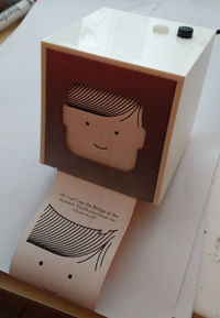 A few years ago a design company from London called "berg" introduced the Little Printer. The device basically is a small printer that prints various feeds provided by berg on a daily basis. Feeds like twitter, newspaper articles, trivia and sudoku. For that it uses regular receipt paper. (promo video) The pricetag was 250 Euros. In 2015 the company went into hibernation but kept the servers running for the rest of the year. Now, in January 2016 the devices are practically useless without the backend servers. I got mine dirt cheap on ebay. HKay |
The Bridge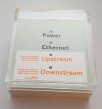 The printer does not talk to the internet directly. That's what the extra box called "bridge" is for. It has a RJ45 connector for Ethernet and a ZigBee module. |
Hardware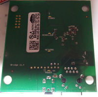 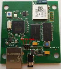 Right from the start the board offers several unpopulated pinheaders for JTAG and SERIAL. A quick check with the Oscilloscope reveals the pinout. And a logic analyser tells us the required baud settings. Baudrate: 115200 8N1 of course no hardware flow control. The voltage levels are 3.3 volts. The board contains the following ICs RAM: 48LC16M16A2 - 256 Mbit FLASH: 29F2G08ABAEA - 2Gb 16bit blocks CPU: ATMEL AT91SAM9620 Ethernet tranceiver: KSZ8041NL ZigBee Module: ETRX357 The rest is voltage regulation and logic To connect to the board via a serial link I used the "SparkFun FTDI Basic Breakout". The RX,TX and ground pins are indicated in the picture above. Connect "RX"(receive pin) to the "TX"(transmit) pin on the FTDI board and the other way around. Also connect GND to GND. Make sure you have the 3.3V version as the 5V version would likely fry the board. |
Software
Here is the boot chatter of the bridge. The system is a AT91SAM9G20 at a clockspeed of 396 MHz running Linux with a kernel version of 2.6.36.4 in April of 2013 It has access to 32 MB of RAM and 256 MiB of Flash (far less than is availible but still great for the purpose). The boot process finishes in a login prompt. The obvious passwords default passwords don't work. Datei:Little printer bridge boot log.txt
However the System boots with an unlocked uboot. The classic INIT=/bin/sh work around can be applied.
When uboot asks you to press a button to stop the boot process for a uboot prompt we enter 'pri to get the boot parameters.
U-Boot> pri
...
bootargs=console=ttyS0,115200 root=/dev/mtdblock6 mtdparts=atmel_nand:128k(bootstrap)ro,256k(uboot)ro,128k(env1),128k(env2),2M(linux),16M(config),-(root) rw rootfstype=jffs2
...
Now we just append init=/bin/sh to the end of the boot arguments. And continue booting.
U-Boot> setenv bootargs console=ttyS0,115200 root=/dev/mtdblock6 mtdparts=atmel_nand:128k(bootstrap)ro,256k(uboot)ro,128k(env1),128k(env2),2M(linux),16M(config),-(root) rw rootfstype=jffs2 init=/bin/sh
U-Boot> run bootcmd
The boot ends in a root shell that we use to replace the current root password and reboot into the regular system.
/ # passwd
Changing password for root
New password:
Bad password: too short
Retype password:
Password for root changed by root
/ # sync
Once the default system is running you cannot make changes to the filesystem. That's why we have to remount it as writeable. Apparently the developer used dropbear to ssh into the bridge. It does not run on boot though. We have to add a init script.
# mount
rootfs on / type rootfs (rw)
/dev/root on / type jffs2 (ro,relatime)
proc on /proc type proc (rw,relatime)
devpts on /dev/pts type devpts (rw,relatime,gid=5,mode=620)
tmpfs on /dev/shm type tmpfs (rw,relatime,mode=777)
tmpfs on /tmp type tmpfs (rw,relatime)
sysfs on /sys type sysfs (rw,relatime)
/dev/mtdblock5 on /opt type jffs2 (rw,noatime)
# mount -o remount,rw /
#
# cd /etc/init.d
# cp S99bergcloud_bridge S99dropbear
# vi S99dropbear
# cat S99dropbear
#!/bin/sh

case "$1" in
    start|"")
        dropbear &
        ;;
    stop)
        killall dropbear
        ;;
    *)
        echo "Usage: S99dropbear {start|stop}" >&2
        exit 1
        ;;
esac
#
# ./S99dropbear
Now we can ssh into the device. There is still a ssh key from the original developer in the system. You might want to remove that file or replace it with your own key.
# rm ~/.ssh/authorized_keys
The Printer
The printer converts the pre-formatted text and prints it onto regular receipt paper. It also has basic software that enables it to print troubleshooting messages along with faces.
Hardware
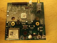
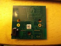
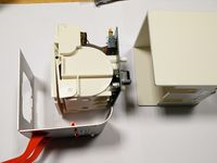
The long FFC connector X1(label hidden) at the top leads to the printer mechanics. right below it is the stepper driver IC "BA6845FS". All the other connectors on the topside are for debugging and therefore not populated. The microcontroller is a Freescale "MC68HC908GP32". Pin 1 is marked by a little dot on the pcb.