Multitouch Table FH Ingolstadt: Unterschied zwischen den Versionen
Huebi (Diskussion | Beiträge) Keine Bearbeitungszusammenfassung |
Bot (Diskussion | Beiträge) |
||
| (11 dazwischenliegende Versionen von 2 Benutzern werden nicht angezeigt) | |||
| Zeile 1: | Zeile 1: | ||
= Git-Repository = |
|||
We created a Git repository for our Multitouch Table Project which contains schematics and layouts for the electronics as well as the source files for our software. |
|||
You can [http://git.bingo-ev.de/fh-in/mtt-projekt.git/ view the repository online] or clone it using the following command (read-only access): |
|||
git clone http://git.bingo-ev.de/git/fh-in/mtt-projekt.git |
|||
= Hardware = |
= Hardware = |
||
Total falsches 3D-Modell: [[File:Mtprojekt-fh-sketchup.skp]] - korrekte version folgt ;) |
|||
| Zeile 43: | Zeile 50: | ||
All electronics hardware in this project was designed using the free [http://gpleda.org/ gEDA] suite which provides tools for creating schematics and board layouts. |
All electronics hardware in this project was designed using the free [http://gpleda.org/ gEDA] suite which provides tools for creating schematics and board layouts. |
||
We have created two boards for the Multitouch Table which are described in the following sections. You can download all files from our git repository |
We have created two boards for the Multitouch Table which are described in the following sections. You can download all files from our git repository. |
||
=== VSync Processing Board === |
=== VSync Processing Board === |
||
| Zeile 228: | Zeile 235: | ||
When everyone is done setting up their area, you can tap the START button to start the game. |
When everyone is done setting up their area, you can tap the START button to start the game. |
||
== Logicsimulator == |
|||
Digital Technologies are highly interesting but sometimes really confusing, especially while learning the basics. |
|||
To understand how combinatorial circuits with some logic gates work, building the circuit would be helpful. |
|||
Unfortunately you'll need hardware, switches, LEDs, wires and maybe some other stuff. Furthermore, it's pretty hard to "look inside" the circuit, and maybe there are mistakes inside it. |
|||
I decided to develop an application, where you can "touch" all the hardware you need to do exactly this, and where you can make all the connections without soldering. |
|||
-> TODO <- |
|||
'''Implemented features:''' |
|||
== Gatterzeux == |
|||
- most common gates (AND, OR, XOR, ...) |
|||
- a selection window for the gates with a slider for the number of Inputs |
|||
- Inputbuttons on the gates you can activate by touching it. The colour (red/grey) indicates the state. |
|||
- the output of the gates is red / grey, indicating, wether the logical condition is true or false |
|||
- you can have several instances of the same gate with a different number of Inputs at one time. |
|||
- you can move and scale the gates as you wish |
|||
'''Not yet Implemented:''' |
|||
- the possibility to connect the gates. |
|||
That means, at the moment you can only try out different types of gates and see how they react on activating their Inputs. |
|||
Unfortunately I'm no professional in developing GUIs, so the sourcecode may be confusing. The time has come for a new version. |
|||
== Swing + MT4J == |
== Swing + MT4J == |
||
| Zeile 331: | Zeile 362: | ||
| ⚫ | |||
== virtual band markus == |
|||
| ⚫ | |||
| ⚫ | |||
= Verantwortliche = |
|||
gabs noch was? |
|||
Projekt der Fakultät Elektrotechnik und Informatik an der Hochschule für angewandte Wissenschaften Ingolstadt. |
|||
'''betreuender Professor:''' |
|||
| ⚫ | |||
Prof. Dr. Bernhard Glavina |
|||
| ⚫ | |||
'''mitwirkende Studenten:''' |
|||
| ⚫ | |||
Tanja Grotter (Projektleiterin), |
|||
Fabian Hübner, |
|||
Daniel Lohr, |
|||
Thomas Jakobi, |
|||
Markus Platzdasch, |
|||
Daniel Reinhard, |
|||
Sebastian Burkhart, |
|||
Thomas Kolb, |
|||
Benjamin Sackenreuther |
|||
Aktuelle Version vom 6. Februar 2012, 15:53 Uhr
Git-Repository
We created a Git repository for our Multitouch Table Project which contains schematics and layouts for the electronics as well as the source files for our software.
You can view the repository online or clone it using the following command (read-only access):
git clone http://git.bingo-ev.de/git/fh-in/mtt-projekt.git
Hardware
MTT-Construction
General Remarks
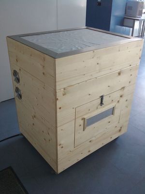
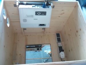
In principle the Multitouch Table (MTT) consists in a box with the multi-touch screen mounted on top in the shape of a cube. For more extensive service work the touch screen can be simply removed from the top. Smaller service adjustments on components like mirror, camera, or beamer can be accomplished via a second service opening on the back of the table. The size of the lower body is defined by the distance of the beamer and the actual size of the touch screen in order to achieve a non-distorted picture. In this respect the actual shape of the lower body may differ when using different components.
Box
All parts for side walls were manufactured using 16mm 3-layer-laminated sheets of wood and for bottom was using 19mm 3-layer-laminated sheets to guarantee maximum stiffness of the corpus. The only exceptions are the square-shaped timber pieces which serve as support for the bottom- and touch screen glass plate.
The cover plate of the service opening on the back is mounted with a hinge band on the bottom and a latch on the top which allows the door to be opened and folded down. A glued wood molding at the inner side of the opening serves as the body stop. Additionally, an air intake filter was installed into the back door. To prevent an overheating of the beamer two ventilators are installed on the side of the beamer’s ventilator air exhaust. At last four wheels were screwed on to the bottom plate.
The electrical supply for all individual components is realized with a rubber sheathed cable for light mechanical stress (3x1,5 mm²). This cable feeds four on the bottom plate mounted sockets inside, of which two can be shut off. The remaining two sockets for beamer and ventilator cannot be turned off in order to allow a period of continued ventilation to cool the beamer down.
The beamer mount consist of a piece of L-shaped bent 2mm thick sheet metal, which is mounted perpendicular onto the center of the front wall and can be tilted. The beamer hangs on an 8mm threaded rod. A lock nut serves to secure and arrest the beamer in its position.
The reflecting mirror is mounted in the center position on the bottom board. Fine tuning of the mirror is achieved by changing the angle via a threaded rod and a butterfly nut.
Touch Screen
Four 20 cm long square-shaped timber pieces were glued to the four corners inside of the touch screen frame. They ensure primarily a tight fit of the touch screen with the lower frame, and secondly protect the circuit boards installed on its backside. The top cover frame is made out of stainless steel. It protects the LEDs and is secured in its place at the corners of the frame. This completes the project.
During every state of the development and construction of the MTT achieving a maximum light density has been a major objective to reach a best quality product.
Electronics
All electronics hardware in this project was designed using the free gEDA suite which provides tools for creating schematics and board layouts.
We have created two boards for the Multitouch Table which are described in the following sections. You can download all files from our git repository.
VSync Processing Board
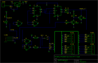
The board can toggle the pulse signal of the attached LED drivers on each VSync pulse of a PlayStation Eye camera, i.e. the camera will take one picture with the LEDs on and one with the LEDs off.
The board features 2 modes of operation: pulsing mode and solid mode. See section #Jumpers / Mode selection for information on setting the mode.
Specifications
- Supply voltage: 24V DC
- Connectors to LED Drivers: up to 4 drivers can be connected. All drivers receive the same signals
- Pulse signal output: 0V/5V (5V means LEDs are on)
- Camera connector: Provides the VSync signal, +5V and GND from the camera.
Jumpers / Mode selection
The board features 2 modes of operation:
Pulsing mode
In this mode, the pulse signal is toggled between 0V and 5V on each VSync pulse from the camera. When running in pulsing mode, you can add an additional 24V supply path for more “brightness” of the IR LEDs.
You can switch the board to this mode by setting the jumper J2 and removing the jumper J1. The additional 24V supply can be enabled by connecting pins 1 and 2 on S1 using a jumper.
Solid mode
In this mode, the pulse signal is permanently set to 5V, which means that the LEDs will be permanently on.
WARNING: DO NOT connect the additional 24V supply in this mode! Doing so might destroy the LEDs or shorten their lifetime!
To disable the additional 24V supply, you can put the jumper on S1 to pins 2 and 3 or remove the jumper completely.
You can switch the board into solid mode by setting J1 and removing J2.
Suggestions for improvement
A short explanation of how the circuit should work
The task of the circuit is changing the state of the output at rising edges of the VSYNC signal. By doing that, the short pulses will change to a long square wave. So the IR-LEDs will turn on / off just before the next image is tanken.
This corresponds the behavior of a T-flip-flop. This T-flip-flop was implemented by two JK-flip-flops and some inverters. The inverters were made from NAND-Gates.
The Problems
As the flashing mode has not yet been implemented in the tracker software, we took only a short test run. It has been shown that the LEDs are flashing, but the picture sometimes is "cut". This means that half of the image is illuminated, but not the other half.
It could not be determined whether the basic approach with the T-flip-flop is incorrect, or the reactions of the circuit are too slow.
Furthermore:
If the installed NAND-gate is replaced by an identical, newer model, the circuit will not work anymore. Apparently, the newer NAND-gates do not react quickly enough.
It must be clarified, if the basic procedure is correct. If so, the circuit must be optimized by:
- faster response to rising edges
- faster NAND gates, or changing to pure inverters.
LED Driver Board
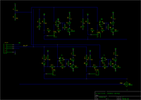
This board drives multiple strips of IR LEDs. Additionally, it can detect failed LED strips and provides a signal input for pulsing of the LEDs.
Specifications
The board was designed for the following environment:
- Supply voltage: 24V DC
- LED Strips: 12x 850nm LED in a row at 50mA current (100 mA in pulsing mode)
- Pulse signal: 0V/5V (5V means LEDs are on)
Failed strip detection
The board contains 4 status LEDs (one for each strip) in the visible spectrum, which light up while a current flows through the corresponding LED strip. If a LED in the strip fails, it's resistance becomes infinitely high and the current through the strip will be zero all the time. The corresponding status LED will therefore be off for failed strips.
Pulsing the LEDs
The LEDs can be pulsed for better filtering of unwanted light sources.
To do this, a 0V/5V square wave should be applied at the PWM pin. For better performance, an additional 24V-Supply voltage can be provided at the 24V_OPT pin, which is used to give additional current to the LED strips.
WARNING: Using 24V_OPT without pulsing can damage the LEDs or shorten their lifetime, because the current is 100mA with this additional supply.
Software
What would be good hardware without just as good software?
For the realization of our programs we used MT4j Multitouch for Java - an open source Java framework, created for rapid development of visually rich applications. MT4j is designed to support different kinds of input devices with a special focus on multi-touch support. Since it would be boring just to use the examples provided like the cool ping pong application, we decided that each team member should program his own app. In the following sections, the applications will be briefly introduced by their developers. I start with the game, I developed and inform you about my approach to programming and describe my problems here. Here we go!
Hatgame
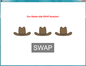
Since games are always good for demonstration purposes, I thought it would be fun to develop one by myself. I chose a simple shell game / hat game ("Hütchenspiel") . The goal of the game is quite simple. The player must guess under which hat is the ball. The program tells him then whether he was right or not. I choose this kind of program, because it shows the usage of simple animations and the right placing of your components in the canvas of your scene. These kind of programs are very good for learning purpose ;D have fun and don't expect to much.
Let's take a look at the interface first:
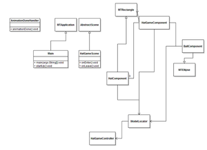
To realize this game several classes are needed, the following picture gives a quick overview:
Every application in MT4j is called a scene and all components like my HatGameComponent, which represents the playing field must be added to the canvas of this scene or be added to components which are then added to the canvas of the scene. I think the diagram explains itself.The HatGameComponent consists of three HatComponents and one BallComponent. Each of these components provide methods for animation purposes, e.g. the lift of the hat when the ball is hidden underneath. In MT4j animation is done by using listeners similiar to swing. There are several listeners to process different kinds of events, like tapping. Let's demonstrate the whole thing by using the lift animation example.
public void animateLift(AnimationDoneHandler callback, int delay) {
       IAnimation lift;

       //1
       Vector3D trg = this.getPosition(TransformSpace.GLOBAL);
       //2
       lift = this.tweenTranslateTo(trg.x,trg.y - 125, 0, 750, AniAnimation.QUAD_IN, delay);

       //3
       lift.addAnimationListener(new LiftAnimationListener(callback, this));

       lift.start();
}
The first step in animation is to get the current position of your component, in our case the HatComponent, which is to be lifted (1). Afterward we use the method tweenTranslateTo to perform a tween translating. Inbetweening - or tweening - is the process of generating intermediate frames between two images to give the appearance that the first image evolves smoothly into the second image(2). Finally we must add an Animation Listener. In our case, it looks like the following:
class LiftAnimationListener implements IAnimationListener{
        private HatComponent c;
        private AnimationDoneHandler callback;
        public LiftAnimationListener(AnimationDoneHandler callback, HatComponent c) {
           this.callback = callback;
           this.c = c;
        }

        @Override
        public void processAnimationEvent(AnimationEvent ae) {
           if (ae.getId() == AnimationEvent.ANIMATION_ENDED){
               c.setSelected(true);
               locator.getController().showBall();


               animateLiftDown(callback, 1000);
               return;

           }
       }
}
But that was until now only the half of the animation. With the code snippets above you only reach a lift up of your compont, in order to hide the ball under the hat you had to do another animation, that lift it down. The code for this problem can be found in my project. The animations was the only tricky thing when writting the program. The tutorials on the MT4j site ([1]) are pretty good, so it would be weak sense to present all contents in this place. I recommend that if you start with the MT4j framework really read the entire tutorial. We are now at the end. You can find my code in our download section. Thanks for reading, if you have further questions and need help with more difficult animations, don't hesitate to write me an email: HideForever@web.de.
In the following sections, the other members of our team will demonstrate their applications and show other aspects of using MT4j as framework.
Multitouch Poker
This is a Poker game for multitouch tables which can be played by a (theoretically) infinite number of players at one table at the same time.
The Startup Routine
Before the game, all players have register at the table by double-tapping on the empty area. When doing so, the player gets assigned an area which contains his/her name and can be dragged around at the table as he/she likes it. The name can be changed by tapping it once.
The main purpose of those areas is to prevent the players from changing positions during the game, as they cannot move their cards out of their area.
When everyone is done setting up their area, you can tap the START button to start the game.
Logicsimulator
Digital Technologies are highly interesting but sometimes really confusing, especially while learning the basics. To understand how combinatorial circuits with some logic gates work, building the circuit would be helpful. Unfortunately you'll need hardware, switches, LEDs, wires and maybe some other stuff. Furthermore, it's pretty hard to "look inside" the circuit, and maybe there are mistakes inside it.
I decided to develop an application, where you can "touch" all the hardware you need to do exactly this, and where you can make all the connections without soldering.
Implemented features:
- most common gates (AND, OR, XOR, ...)
- a selection window for the gates with a slider for the number of Inputs
- Inputbuttons on the gates you can activate by touching it. The colour (red/grey) indicates the state.
- the output of the gates is red / grey, indicating, wether the logical condition is true or false
- you can have several instances of the same gate with a different number of Inputs at one time.
- you can move and scale the gates as you wish
Not yet Implemented:
- the possibility to connect the gates.
That means, at the moment you can only try out different types of gates and see how they react on activating their Inputs.
Unfortunately I'm no professional in developing GUIs, so the sourcecode may be confusing. The time has come for a new version.
Swing + MT4J
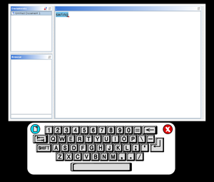
MT4J offers the possibility to integrate Swing Components and thereby enables the user to include existing applications or single Swing components. To display these components, MT4J provides a SwingTextureRenderer-Object. In a sample application, the SwingTextureRenderer was added to a MTTextKeyboard as a child component, PersistentContentPane is a Swing object:
public void addImage(PersistentContentPane cp) {
    swing_app = cp;
    str = new SwingTextureRenderer(app, swing_app);
    str.scheduleRefresh();
    final MTImage m = new MTImage(app, str.getTextureToRenderTo());
    m.setPositionRelativeToParent(new Vector3D(100, -100, 0));
    this.addChild(m);
}
During the evaluation of the SwingTextureRenderer, especially 2 things were of great interest:
- which rendering update frequency is necessary, to provide a smooth user experience, is the
- performance of SwingTextureRenderers sufficient for that
- how is it possible, to forward MT4J user input to the swing application
concerning 1. An update-rate of 150ms has proven to be appropriate, however higher rates were possible as well, 100ms and even below. A possible pitfall is the code-location, in which the scheduleRefresh-method of SwingTextureRenderers (str) is invoked. The method may only be called in the updateComponent-method of its parent-object (in this case: MTTextKeyboard)
@Override
public void updateComponent(long timeDelta) {
    if (str != null) {
        totalDelta += timeDelta;
        if (totalDelta >= 150) {
            totalDelta = 0;
            str.scheduleRefresh();
        }
    }
    super.updateComponent(timeDelta);
}
concerning 2.
In the example only keyboard input was considered, meaning that touch-gestures on a Swing-component were
no forwarded to swing as mouse event.
As a first step, the objective was setting the focus to the Swing-component, which was supposed to process the key events.
In the following, the events were just pushed into the event queue.
protected void onKeyboardButtonClicked(MTKey clickedKey, boolean shiftPressed) {
    /* submitKeyEvent(char newChar) */
    final String newChar = clickedKey.getCharacterToWrite();

    Toolkit toolkit = Toolkit.getDefaultToolkit();
    EventQueue queue = toolkit.getSystemEventQueue();

    try {
        SwingUtilities.invokeLater(new Runnable() {

           public void run() {
	    swing_app.getEditorWindow().getTextPane().requestFocusInWindow();
	    queue.postEvent(new KeyEvent(swing_app.getEditorWindow().getTextPane(),
                                           KeyEvent.KEY_TYPED,
                                           System.currentTimeMillis(),
                                           0,
                                           KeyEvent.VK_UNDEFINED,
                                           newChar));
                                                           }
    });
    } catch (Exception ex) {
    }
    System.out.println(newChar);
}
Unfortunately, this solution turned out to be a dead end. The events could't be dispatched/processed by the Swing-component. A possible way to go, is sending the event not to the Swing-component (e.g. JFrame) itself but to the underlying document-object.
protected void onKeyboardButtonClicked(MTKey clickedKey, boolean shiftPressed) {
    /* submitKeyEvent(char newChar) */
    final String newChar = clickedKey.getCharacterToWrite();

    try {
        SwingUtilities.invokeLater(new Runnable() {

            public void run() {
                swing_app.getEditorWindow().getTextPane().replaceSelection(newChar);
                swing_app.getEditorWindow().getTextPane().updateUI();
            }
        });
    } catch (Exception ex) {
    }
    System.out.println(newChar);
}
Links
- FTIR_Multitouch_Table (german)
Verantwortliche
Projekt der Fakultät Elektrotechnik und Informatik an der Hochschule für angewandte Wissenschaften Ingolstadt.
betreuender Professor: Prof. Dr. Bernhard Glavina
mitwirkende Studenten: Tanja Grotter (Projektleiterin), Fabian Hübner, Daniel Lohr, Thomas Jakobi, Markus Platzdasch, Daniel Reinhard, Sebastian Burkhart, Thomas Kolb, Benjamin Sackenreuther
